This is my first transmitter/transceiver construction project for over a decade. The “Stone” is a QRP double conversion superhet SSB transceiver for 40m based on a kit from Tim Walford. Tim, G3PCJ, takes you step by step through the build, explaining how to test each stage.
I’ve added a three digit frequency counter and an automatic gain control from Tim’s kits and a phasing notch filter from a design I’ve used a number of times. The rig “comfortably” puts out 1w SSB (it will do more) which I’m feeding into Tim’s linear kit (ex-Cam transmitter project) to put out 20w.

Tim’s Design
The RX uses an IF of 6MHz with the VFO running near 1MHz. It has a double tuned RF filter feeding the first SA602 mixer with input from the VFO, outputting to the second SA602 with a 6MHz crystal controlled carrier oscillator.
The TX feeds the second mixer above now suppressing the carrier and removing the upper sideband by the IF filter. It is then mixed with the VFO in the first mixer above. The RF driver stages feed a IRF510 power amplifier which is followed by low pass filter.
Tim’s kit is shown below although this photo is the 1.5w version

The VFO covers 7.0-7.2MHz in one 180 degree sweep of a variable capacitor with an additional fine tuning. This makes frequency calibration on the dial difficult to achieve with much accuracy so this project will include a frequency counter.
Tim’s counter kit is shown below without all the wires to the LED digit displays.
Case Planning
Planning stage
I bought the case before building the radio and whilst it has worked and looks fine, a slightly larger case would have been easier to fit all the bits. The learning here is that choosing the case should be the last step!
Main Tuning
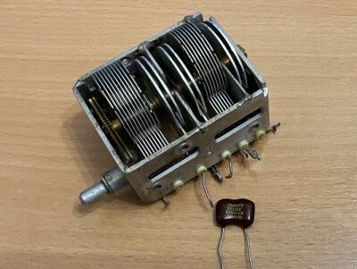
I was planning to use a 265pF air spaced variable with geared drive for Main Tuning and dispense with fine tuning but it wouldn’t fit in the case.
Just in “case” it would fit, my plan was to meet my target capacitance range for the tuned circuit which is 390 – 510pF. That should be possible with putting this in parallel:-
375pF from the static caps in the Stone and then the air variable and a 560pF fixed cap in series. The fixed cap is hugely overspec but I had it and it should have worked well.
Finished Radio
I created a mezzanine arrangement to get all the boards in the case.

Frequency Counter Build
Stage 1 : establish a regulated 5 volt supply
- First I put the caps in the wrong place!
- 5v measured at point “5”
Stage 2 : fit the crystal reference oscillator and divider to produce a 200Hz clock
- listened on 3.2768MHz – touching pin 9 (as an antenna!) and I could hear the oscillator.
Stage 3 : fit timing aspects
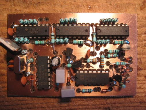
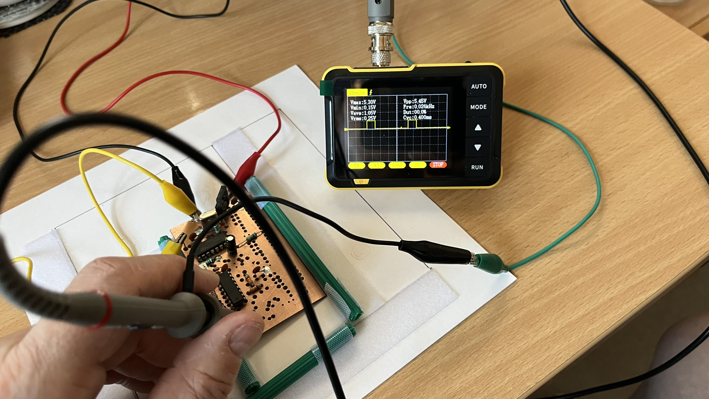
The 200 Hz clock is first divided down to 100Hz in IC2A and then feeds the quinary section. The first stage of that (A output) produces the twin 10 mS positive pulses that are used to reset the counter just before the main counting period of 10 mS during count value number 4, which is derived from the B output. This is a positive pulse of 10 mS which is inverted by TR3 to produce the negative 10 mS period at point C that allows the counting activity by the pre-scaler stage IC2B. At the end of the counting period, the value is stored by the Len bar signal going low during the next count value 0 – since there is not a dedicated output for this, D3/4/5 decode the value of 0. The B output of IC2A (period 2) is a convenient point to initiate a hold delay of about 250 mS while C4 charges up through R3 – during this time D1 stops the crystal oscillator clock. D2 ensures a quick discharge when the clock restarts ready for the next cycle.
- test voltages were wrong – I found I’d reversed diode D3!
- point “R” (reset=IC2pin5) was now reading 1.97v
- point “L” (LenBar) voltage was wrong – R5 needed resoldering to ensure it was earthed on the plated through connection – now 3.38v (this is slightly lower than I expected)
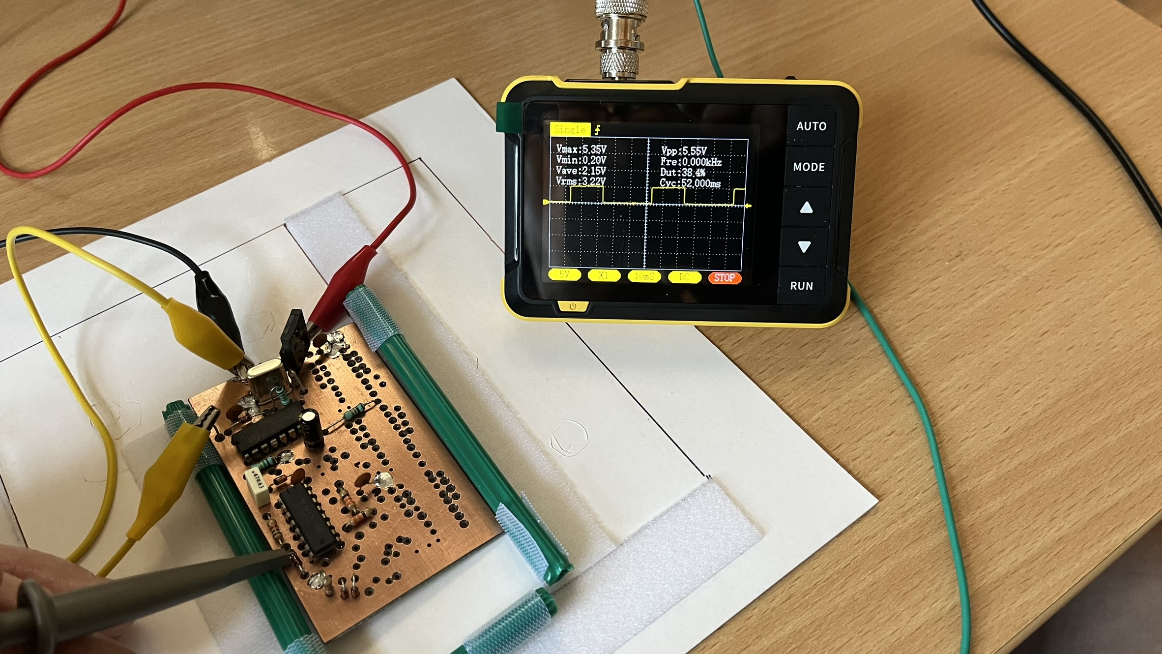
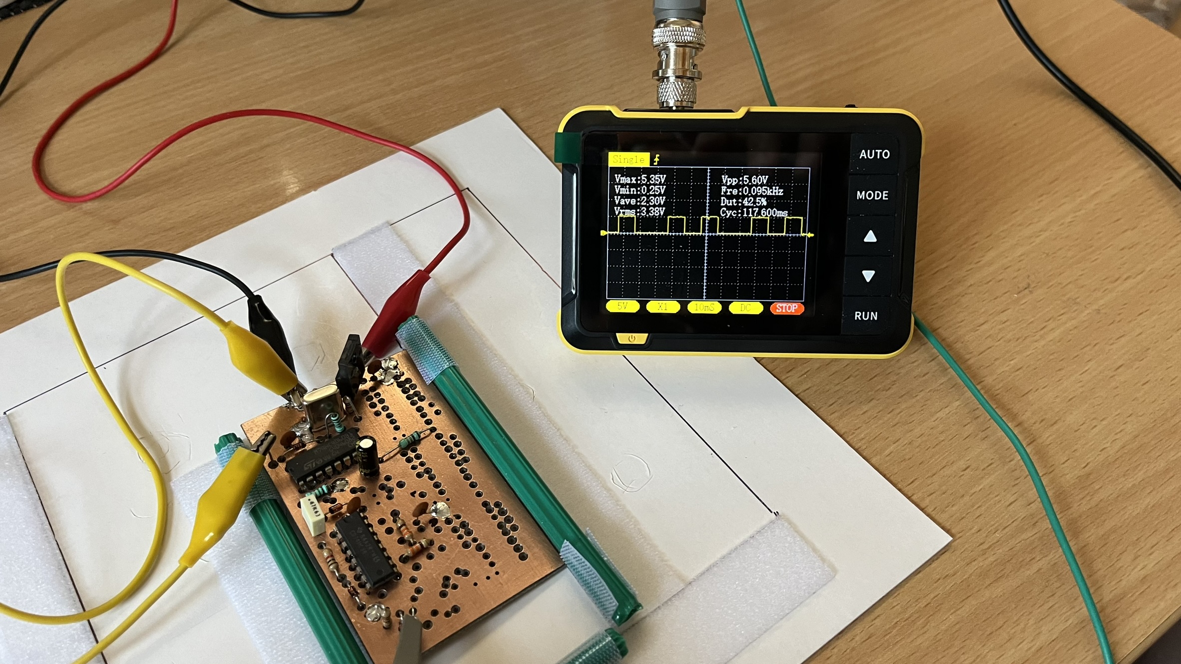
Realising I needed to see what was going on on a scope I bought a very inexpensive FNIRSI DS0152 Mini Oscilliscope as my two big scopes are in storage and so big! This little device only has a 200kHz bandwidth but that’s fine mostly for my purposes through construction. For checking RF I use my TinySA Spectrum Analyser (with thanks to OZ7OU for his write up).
Everything checked out fine

Stage 4 : fit the amplifier
I fitted the transistors in the wrong place, ie. swapped BS170 and BC182! This started a real headache as I replaced the BC182 with a BC182L. The BC182L has different pin-outs!

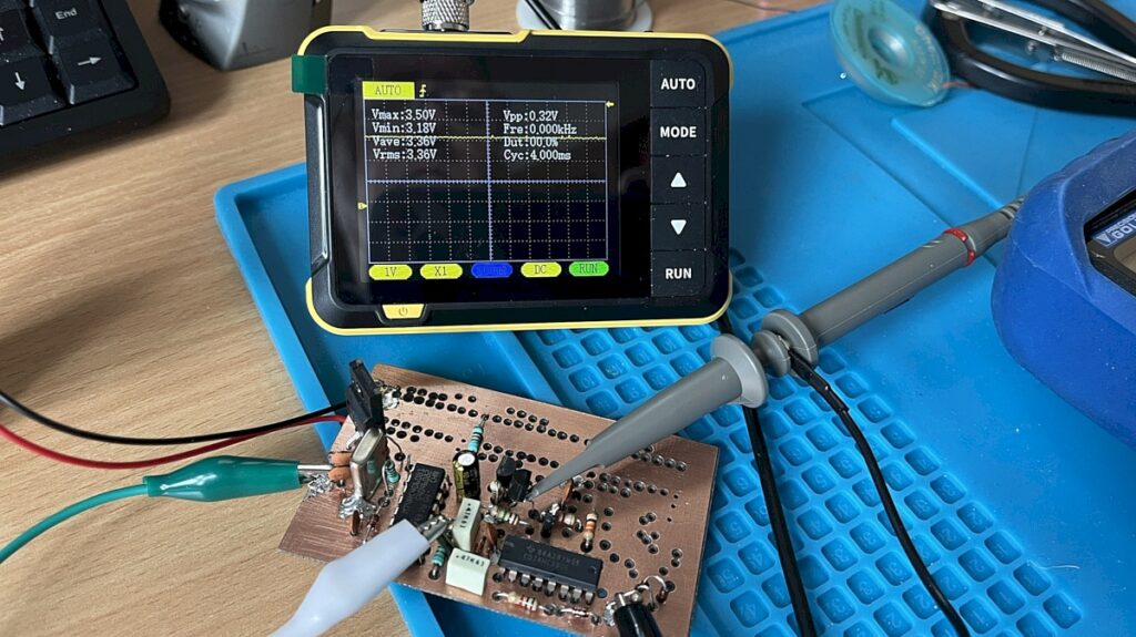
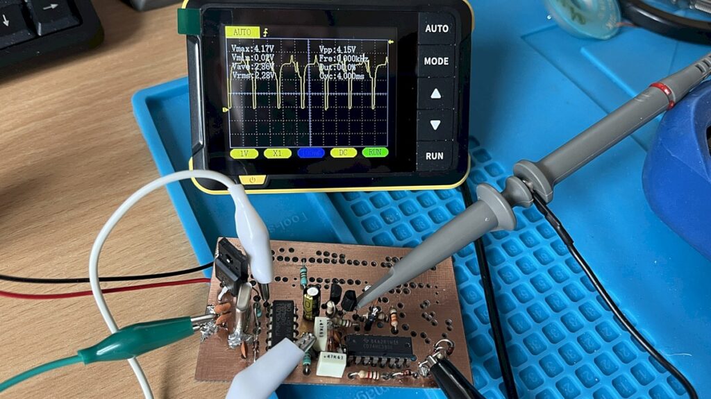
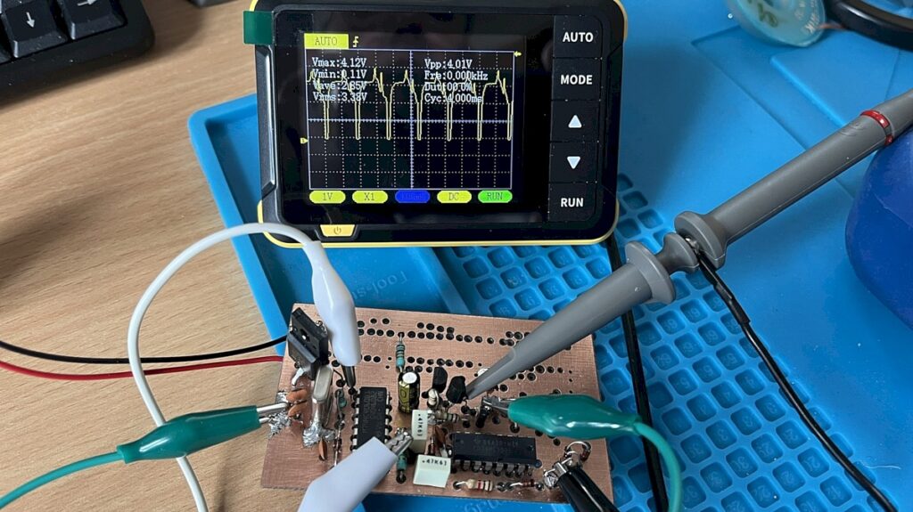
Output on pin 9 of IC2 is showing a signal at 327KHz on my TinySA Spectrum Analyser (with thanks to OZ7OU for his write up)
Stage 5 : fit the counter digit drivers
I then added the counter digit drivers stage and tested with the 3.2768MHz signal from IC1 pin 9 at Input and point C grounded; the 3 MHz overflows and then IC6 deals with the 2, IC5 deals with the 7 and IC4 deals with the 6.
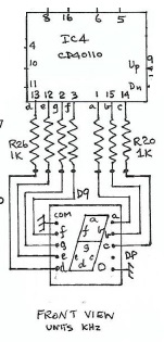
Checking the voltage on each Digit’s ICs pins confirms everything is correct, There should be near 5v on a pin when its corresponding LED bar should be lit.
IC6 should show “2” on the display
IC6 5v at pins: 1,2,12,13,15
IC6 0v at pins: 3,14
IC5 should show “7” on the display
IC5 5v at pins: 1,14,15
IC5 0v at pins: 2,3,12,13
IC4 should show “6” on the display
IC4 5v at pins: 1,2,3,12,13,14
IC4 0v at pins: 15
All tested fine 🙂 I’d stupidly fitted IC6 the wrong way round (before powering up) and had to desolder and refit so I had huge relief when I found it worked.
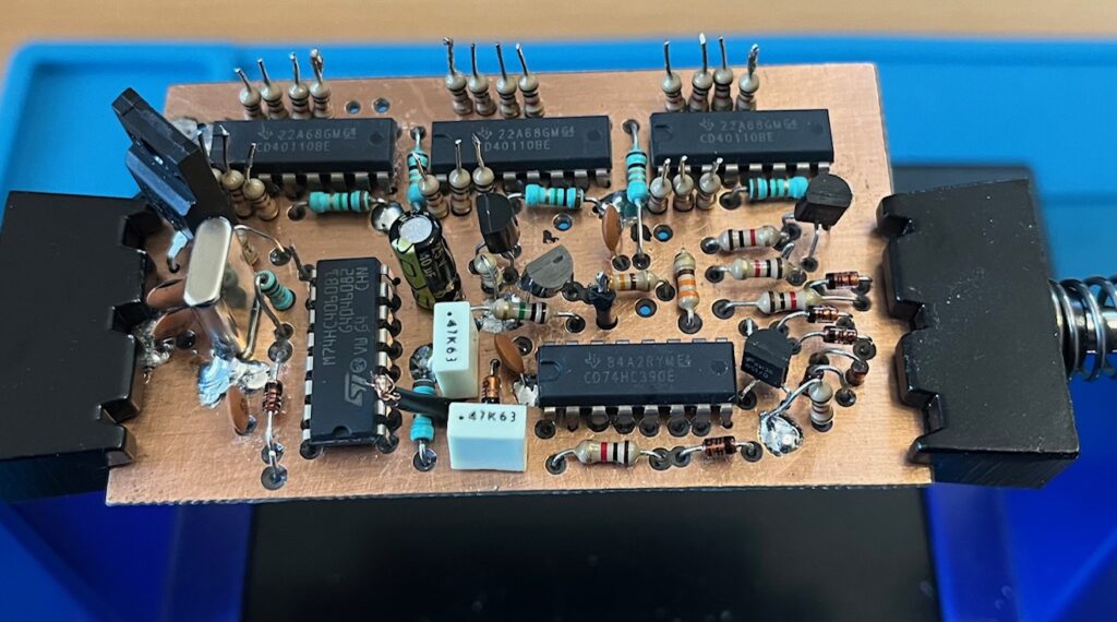
Despite me making far too many errors along the way I got to a successful end point. I suspect my eyesight needs some more assistance than I realised! This board is now complete and ready to be installed.
I’m sitting the board on a mezzanine above the RF and IF stages of the receiver where it will have a short path to the oscillator frequency. The input connector (yellow wrap) and power connectors are plug types enabling quick disconnection from the radio.
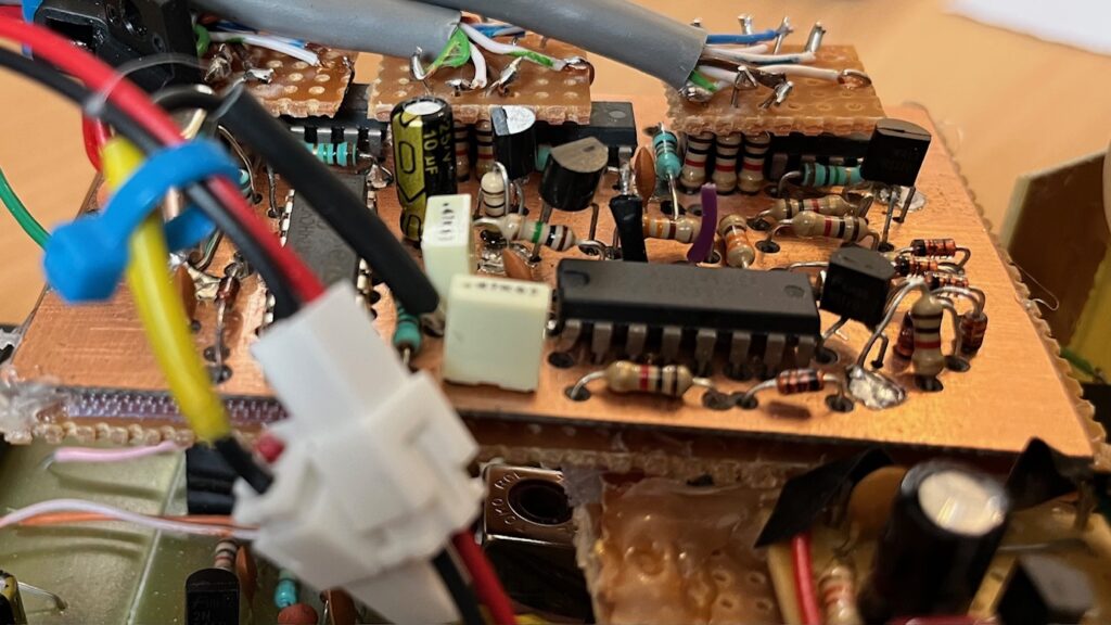
I used perf board above each of the driver chips to give more mechanical strength for the cables but there are a lot of wires in close proximity! I’m mounting the LED digit display above the Fine Tune control which is directly in front of the counter board.
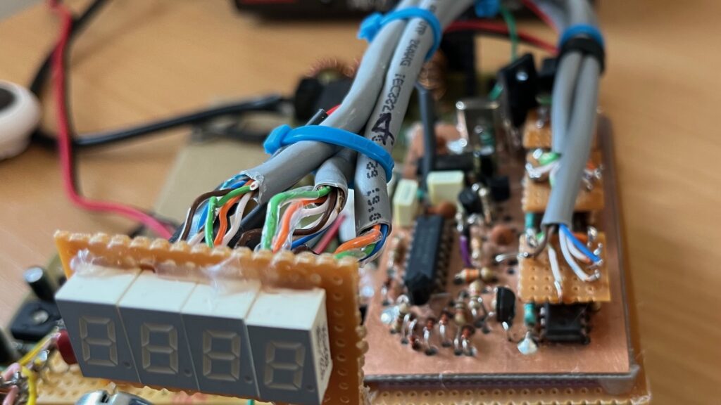
Stone SSB Receiver Build
Receiver Description
RF from the aerial goes through a bandpass filter into the first mixer, subtracting the VFO running at 1.0-1.2 MHz (which provides input to a frequency counter). The product of the first mixer is at the IF of 6MHz. A 4-pole crystal ladder filter network strips off the unwanted passband and signals are then fed into the second mixer/product detector which inserts a 6MHz carrier to produce audio frequencies. These are fed into an audio pre-amp (optionally then to AGC and notch filter) to the AF gain and then through the audio amplier.
Mechanical set up
First build the receiver open style without reference to the case. This starts with fixing the polyvaricon capacitor, two potentiometers and phone socket to the front panel.
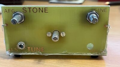
The ground connections to the tuning cap, AFG pot and phone socket are then soldered.
Stage 0 – fit the larger parts
This stage covers the connectors for power and antenna, the RF bandpass filters and the CIO trimmer cap.
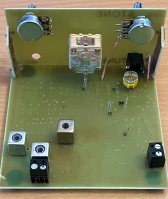
Stage 1 – Power Supply
The parts for the power supply were fitted. A LM317L is used to regulate the voltage. Point 1 (white-green) is connected to LHS tag (viewed from back) of the fine tune pot R8 and point 6 (green) is connected to the RHS tag (viewed from back) of the fine tune pot R8; this presents a 12k load to the voltage regulator. Powering up with 9v DC, point 8 (output from the voltage regulator) shows 7.6v – tested okay.
Stage 2 – Audio Amplifier
The audio amplier parts were fitted with the output connected (green) to the tip contact of the phone socket. Powering up with 9v DC, a click is heard in the phones and pin 5 of IC4 the LM386 amplifier chip shows 4.5v. Finger touching either side of R16 gives a hum in the phones – tested okay.
Stage 3 – Second Mixer
IC2, the SA602 second mixer was installed to provide bias for the audio pre-amp. Powering up with 9v DC shows pins 1 and 2 at 1.4v and pins 4 and 5 at 5.7v – tested okay.
Stage 4 – Audio Pre-Amp
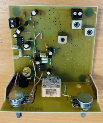
The Audio pre-amp (TR3) uses a BS170. Touching pin 2 of IC2, the SA602 mixer, whilst advancing the AF Gain should significantly rise the mains hum in the phones. I found however that it goes into oscillation and touching the pin has no effect!
Tim advised the voltage regulator needed a minimum of 2 volts headroom above the desired output voltage so 9v wasn’t enough. I increased the voltage to 12v it then tested okay!
Stage 5 – Carrier oscillator
A 6 MHz crystal is used and the tuned circuit trimmer cap was set to minimum capacity. The DC output of the tuned circuit at point C measured 7v and the carrier frequency was detected at 6.005 MHz on my scope.
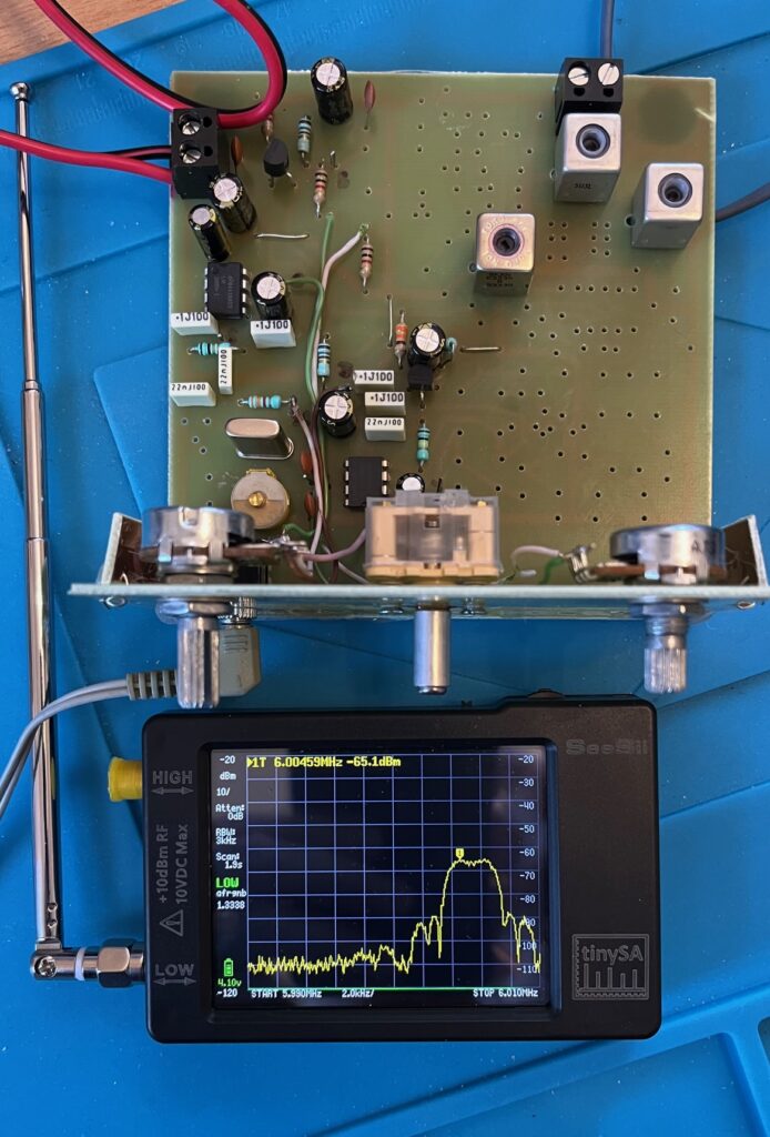
Stage 6 – Intermediate Frequency Filter
The four 6 MHz crystals were fitted and I set my signal generator (the same TinySA) to put out an AM signal on 6 MHz – that came through nicely on the Stone.
Stage 7 – First Mixer and IF Amplifier
The mixer IC1 is another SA602 and the amplifier TR2 is a 2N3906. Voltages tested: 1.44v at pins 1 and 2 of IC1, 6.49v at pin 4 of IC2, 6.44v at pin 5 of IC2, 6.6v at point L and 3.48v at the collector of TR2.
The IC2 voltages should be equal – they are almost. Point L is the buffered oscillator frequency used in the frequency counter – its voltage is slightly low at 6.6v (should be 7 – 7.15v). Although lower than expected, I carried on.
Stages 8, 9 and 10 – Variable Frequency Oscillator
The oscillator is a Hartley type intended to cover a span of 200 kHz between 1.0 and 1.2 MHz.
Inductance: L3 Toko 3333 is 45uH across the primary (55 turns – pins 1-3) which is tapped at 14t between pins 1-2. There are 14 turns on the secondary (pins 4-6)
Capacitance: 150+150+75+Polyvaricon(15-150)=375-525pF The 150pF ceramic caps are N150 types (negative temperature coefficient) for frequency stability.
Target resonance (without trimming etc): 1.035MHz – 1.225MHz
The brown lead goes the slider of the fine tune pot which adjusts the voltage on the power diode D2 acting as a varactor diode, tweaking capacitance of the tuned circuit. The pink lead goes from the tuned circuit (top) to the main tune capacitor.
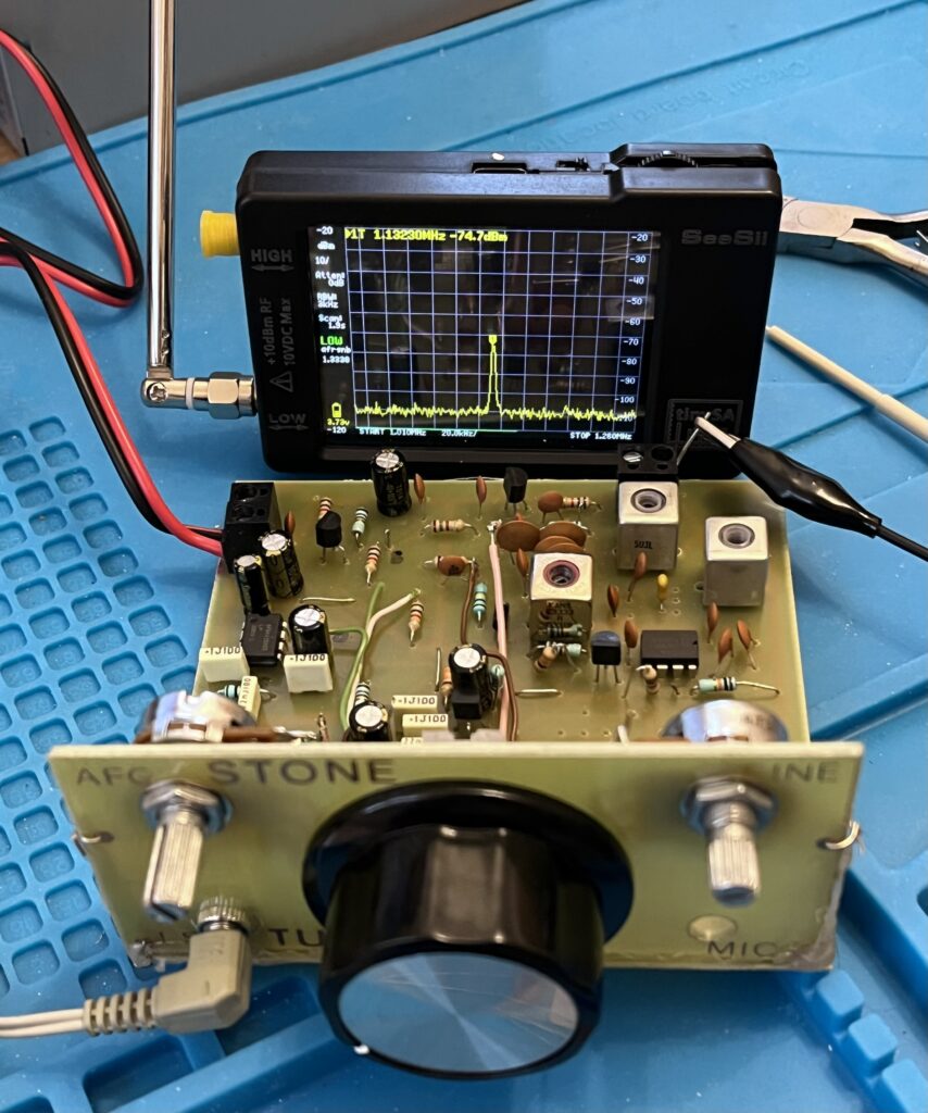
I tracked the VFO oscillator frequency using the TinySA to determine receiver frequency (1,132 MHz + 6 MHz = 7.132 Mhz).
The Toko 3333 was tuned to align the LF edge of the band coverage to the frequency required.
Band coverage is initially around 235kHz and main tuning was a bit keen (pink lead) but doable using only the larger cap in the polyvaricon. Fine tuning (brown lead) is very effective and covers around 12kHz.
Tests:
- Grounding the oscillator at point X causes the voltage at the drain of TR1 to drop from 8v to 7.88v = ok
- Checking voltages on my scope with divide by 10 probe:-
voltage at point Y = 1.35V p-p = ok
buffer output (mixer IC1) point L = 300mV p-p = a bit low!
Stage 11 – Band Pass Filter
Adding the caps, the receiver bursts into life. Two actions now became necessary:-
- The RF coils L1 and L2 needed peaking
- The Carrier Insertion Oscillator trimmer needed adjusting to make LSB intelligable.
There was a faint digital type noise in the background. I found grounding the can of X1, one of the crystals in the 6MHz IF filter, took that noise down appreciably.
Receiver performance
Purely subjectively, sensitivity and audio quality are very good. I heard some QRM from adjacent channels but then I had the same problem the day before using my FT-990. However if there are any problems this is where the phasing notch filter should help.
Radio went deaf
A few days later L2, a 5.3uH coil, seemed to have developed a fault. The receiver went deaf. It was just about possible to detect faint signals that were s9+20 on another receiver but otherwise nothing. It was clear that the audio amp section was fine when applying a finger via screwdriver to that section. The two oscillators were evident too on my TinySA analyser. The problem focused on the RF BPF to the first mixer.
Tracking with dabbing the aerial on junctions in the BPF was inconclusive but I decided to disconnect L2. I didn’t immediately have an equivalent and so replaced it with a Toko 3335. The receiver burst into life again although it is clear that it needs more inductance and it was replaced later with a Toko 3334.
Frustratingly, the problem recurred the following day. I disconnected L1 and L2 and checked their resistance and inductance and they were fine (as was the original L2 coil). Ultimately I put the original coils back in and it worked! My assumption was that L1 pin 3 had a dry joint but the symptoms suggested there was another problem which seemed to have been resolved.
Two days later a degree of deafness returned. I focused on the first mixer and redabbed its solder joints with no improvement so then decided to change the SA602 for another one and the receiver came back as good as ever!
The deafness returned after a few days. I rigged up my 10MHz oscilloscope ready to check the signal path and would you believe it, the receiver was working fine again! So I took some benchmark measurements in case the deafness issue returns.
C7 BPF coupling to IC1 : 4mV p-p wave at approx 7MHz
IC1 pin 5 osc output to buffer : 30mV p-p
C8 VFO coupling to IC1 : 400mV p-p at approx 1.2MHz
IC2 pin 4 : mixer output to buffer – 5-10mV p-p AF
TR3 mixer buffer to AFG : source 40mV p-p AF, drain 150-250mV AF
Freq Counter output: 90mV p-p at approx 1.2MHz
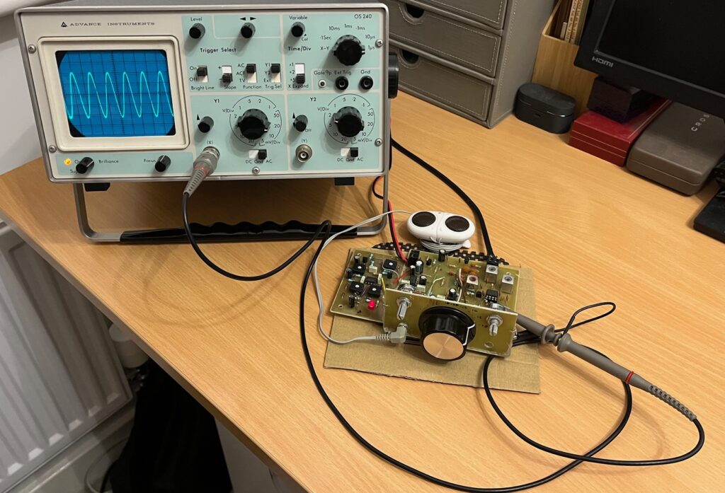
Deafness was later replaced with muteness! I traced the signal route and the cause appeared to be L1 a Spectrum 5uH transformer in the BPF although while off the board it checked out for inductance and resistance. My conclusion is that there is something amiss inside its can which causes a problem on occasion when the board is turned upside down.
Adding AGC
Circuit Description
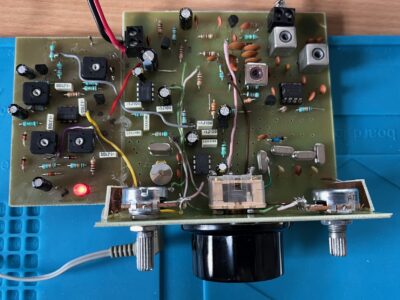
Audio is taken from the receiver’s AF pre-amp output (grey lead) where it used to feed the +ve end of the AF Gain pot. The output from the AGC (yellow lead) goes back to the +ve end of the AF Gain pot.
The AGC limits the audio output to a level preset by a pot. It does this by amplifying all signals and then signals louder than the preset level trigger a feedback loop to attenuate them. It works remarkably well; AGC recovery is about 2 seconds.
There is provision in Tim’s kit to drive a crude S-Meter (either LED or real meter) for signals above around s6 which is very useful and also to show relative power output through the same LED or meter too.
Adding a notch filter
I decided to build the simple audio filter circuit that I’ve used before in the Sutton transceiver project and as an add-on to my Yaesu FRG-7 receiver. The circuit was designed by Richard Booth G0TTL and is a phasing audio notch filter.
As the circuit is an identical build it is described in my previous article: https://m0ezp.squirrelhouse.biz/frg-7-adding-a-notch-filter/
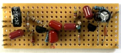
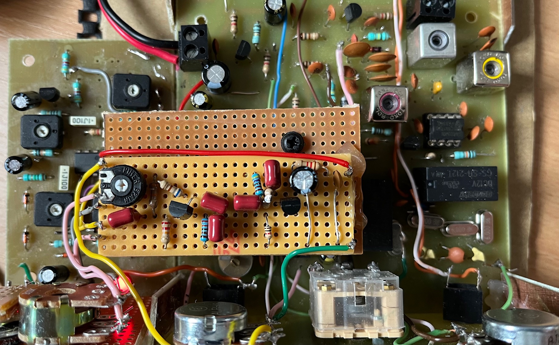
The filter will be connected between the AFG slider and the AF amplifier.
LHS connectors from top to bottom:-
- Output – to AF volume control pot top end (note: the slider goes to the AF power amp)
- x
- x
- Notch end VR-A
- Notch common slider to VR-A and VR-B
- x
- Input – from AGC output (which went to the AF volume control previously)
- Notch end VR-B
- Ground (later this pin was removed to create space)
RHS connectors from top to bottom
- 2nd row down: Ideally 12v but 10.5v works fine
- Bottom row: Ground from external DC input connection
The board is sitting on a “mezzanine” pedestal over the receiver PA section being careful not to obscure any pre-sets.
Stoke SSB Transmitter Build
Transmitter Description
The Stoke is dependent on the Stone RX board. Microphone audio is amplified and mixed using the carrier and IF strip from the RX. Control is managed from PTT by relays switching the signal flow, mute and power.
Stage 1 – DC Supply
Fitting the DC supply parts. With a DC voltage of 12.25 input, the +ve end of R52 was exactly half at 6.12v.
Stage 2 – Speech Amplifier
The DC voltage at point H measured half the input at 6.12v.
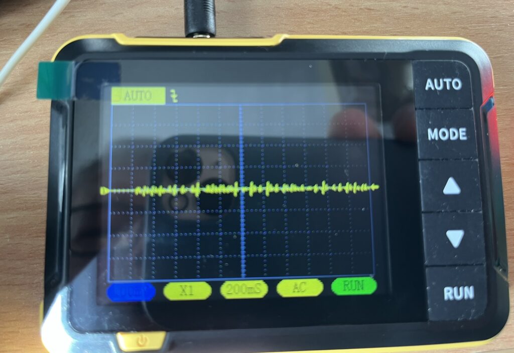
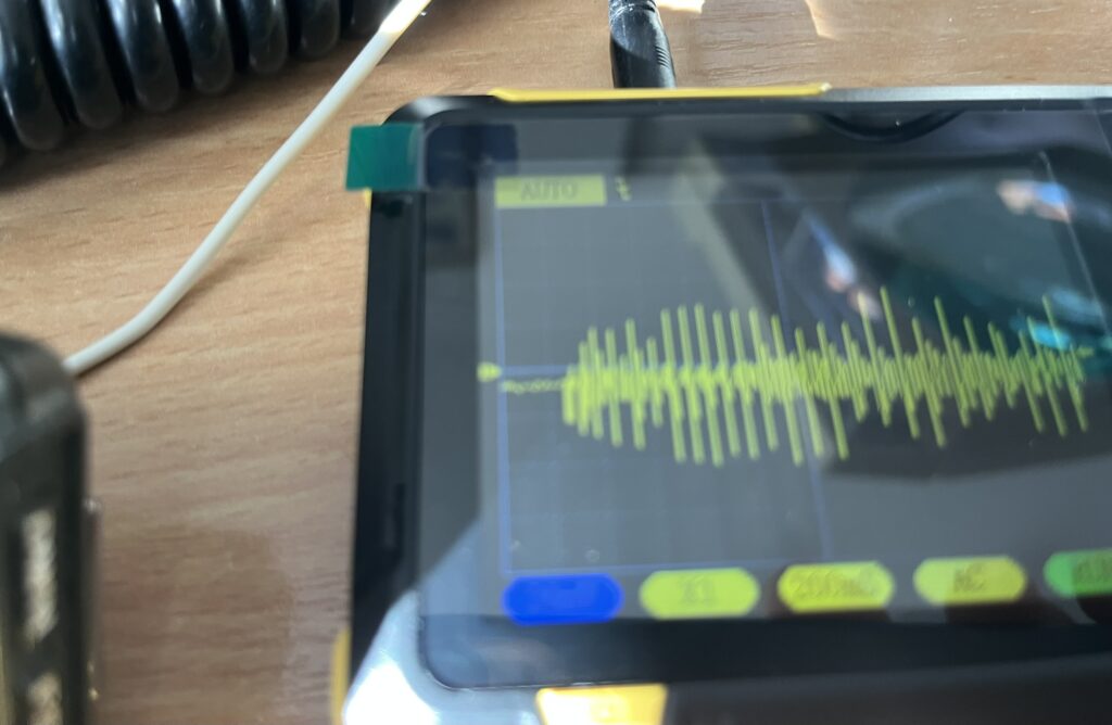
Feeding audio input at point M, the amplifier could be seen to work on the mini-scope and be responsive to the mic gain preset R54A.
Stage 3 – PTT Control
When P is grounded, the two relays click on and the voltage at point T rises from 0v to 8v.
Stage 4 – RF Pre-Amplifier
The drain of TR52 (at the junction with R61 and C60) was 5.5v
Stage 5 – RF Amplifier and Buffer
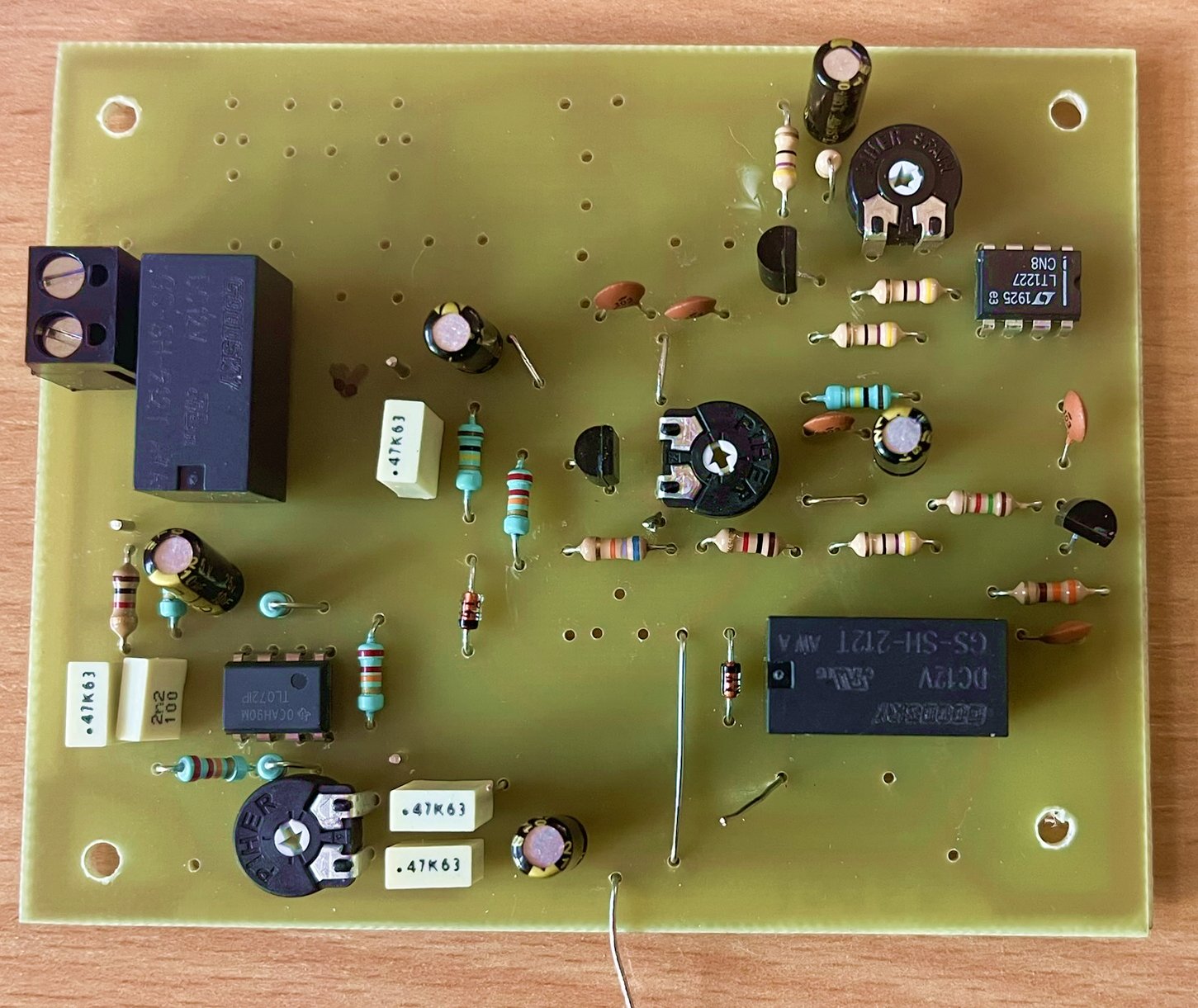
This test is to check the bias control is effective. Voltage is checked at point N the gate input to TR54, the IRF510 power amplifier (not yet connected). It measured 4.5v at full clockwise of R59 bias preset pot.
Stage 6 – Fit the RF output stage
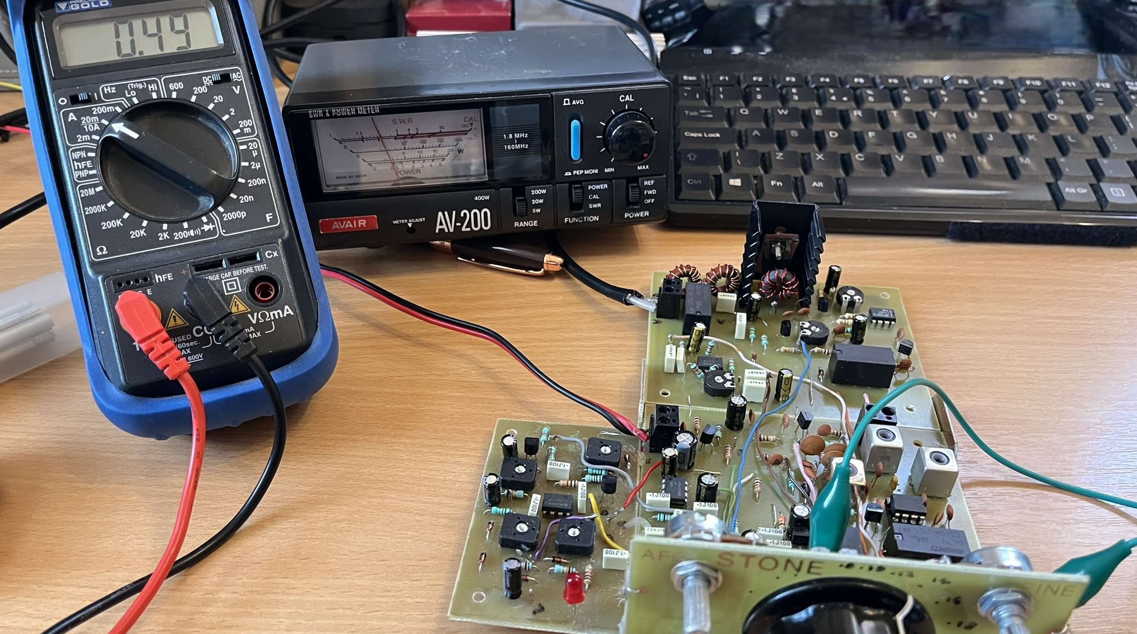
I made a bifilar wound output transformer, I connected that and the IRF510 + heatsink. I measured current draw which was 22.7mA with all preset pots anticlockwise. Whilst grounding the PTT point P current rose to 47.5mA. Advancing R59 bias preset to full clockwise briefly brought current to 490mA.
Bifilar Transformer construction
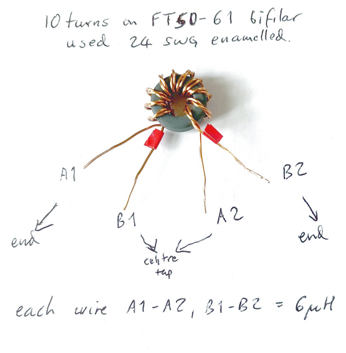
I made a transformer using 24 gauge enamelled wire wound bifilar with 10 turns.
I used 50cm of wire, folded into two with a loop in the middle then clamped the two free ends using a vice. I slotted a screwdriver through the loop and twisted until I got around 4 twists per inch. I cut the loop and checked continuity of each wire so I could tell them apart.
Useful link: how to wind bifilar although using a drill seems a bit overkill for 10 turns.
Stage 7 – Fit the LPF
The LPF for 40m uses 2 x 820pF capacitors in series (1640pF) at either end and 820pF in the middle with 2 x coils at the top of 14 turns of 24G enamelled wire on a FT50-61 toroid.
Stage 8 – Fit the PTT control relays
The relays on the Stone RX board switch the signal direction through the IF strip when PTT is grounded.
This was tested by checking the VFO frequency eg. 1.34 MHz and setting up a receiver on the 7.34 MHz; then grounding point 7 which unbalances the mixer to produce crude CW; then grounding PTT. A carrier was detected on 7.34 MHz so the test works!
Stage 9 – Connect the RX and TX boards together
The two earthy parts of the boards were connected together first with multiple connections and wire links. Power was connected next – I used thicker wire on the underside of the board to make for a better connection.
The mic socket with PTT was fitted with (tip) mic to TX point M input to the speech amplifier and (ring) PTT to TX point P the Tx/Rx control.
Output from the speech amp point B was connected to the RX Mixer IC1 point B via relay control. The route goes to the left of RL50 and (unwisely) I used a brown wire; there’s another brown wire in this route from RX point 6 to Fine Tuning so be careful when maintaining!
RX aerial connector is now connected to TX point R which uses Tx/Rx control.
RX Muting is done by connecting TX point T to RX point T under PTT control.
Microphone adaptor cable
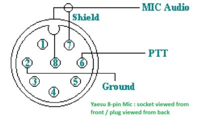
As my microphones all use Yaesu 8-pin plugs I constructed an adaptor cable to the 3.5mm mic connector on the front panel:-
- Mic audio – white wire to 3.5mm tip
- PTT – red wire to 3.5mm ring
- Ground – black wire to 3.5mm sleeve
Two Tone Test Results
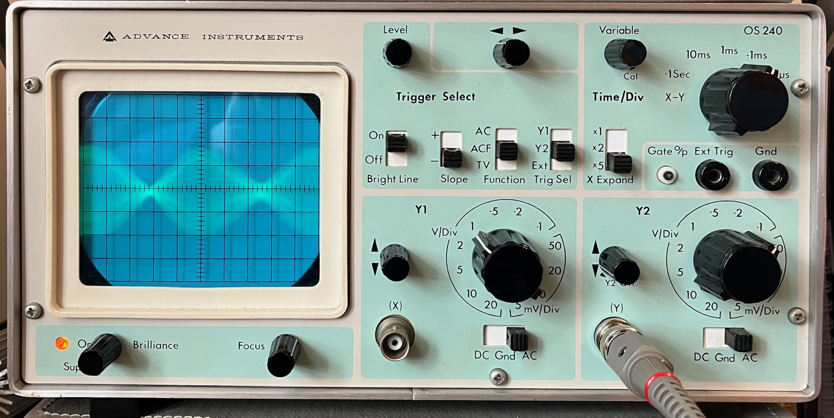
As I don’t have a tone-tone oscillator for audio input I improvised with using a two tone audio file I found on the internet and playing that from my iPad, feeding audio into the mic socket. My scope is over 50 years old and stability isn’t great however I can see that the signal isn’t flat topping and looks good.
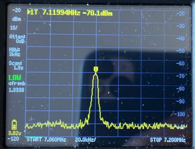
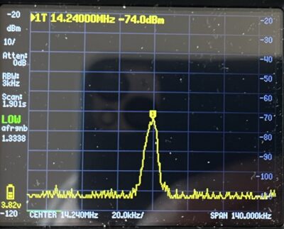
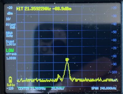
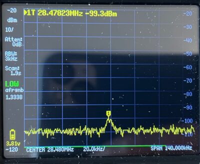
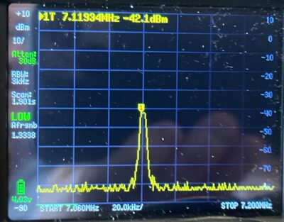
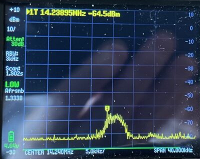
I looked at spurs and harmonics and overall the output was fairly clean. I have put some specifics below (using my TinySA spectrum analyser transmitting into a dummy load):-
Using Commercial 50w Linear with LPFs
Alignment
23 June 2025
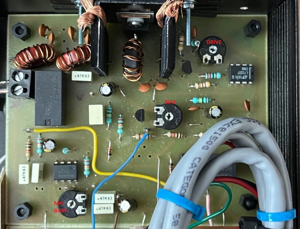
Current readings:-
RX only = 140mA
TX no bias = 190mA
TX add 0.4A = 600mA
Drive to 2.25W (two-tone) = 1.25A
Using Adonis mic in SSB position with about 60% volume gives about 1w peaks