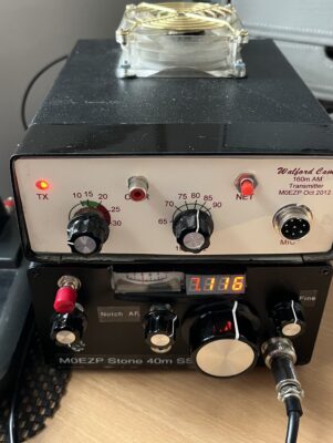
I intended to use a commercial low power linear amplifier for my Stone SSB transceiver and the Micro PA50+ seemed exactly what I needed. However, that amplifier turned out to be very susceptible to external RF and other issues that make it impractical. After a few weeks of trying to use it and some minor modifications, which did improve it but not enough, I gave up.
I decided to repurpose my Cam 160m AM transmitter project built in 2012 which included a linear amplifier. On 40m I’m expecting output to be lower than the 35w it put out on 160m but should deliver 20-25w SSB output.
The Cam transmitter was unlikely to be used again due to moving QTH and not having the same opportunities for outdoor antennas coupled with the high levels of domestic/neighbouring QRM. The linear amplifier part of the project would be ideal for my Stone SSB transceiver. To do this it had to be converted to make it an independent module rather than its intended design which was to be integrated more tightly with a transmitter using its TR control, Bias control and LPF. I decided to keep the front panel, for old time’s sake but electrically disable the transmitter.
Walford Linear Amplifier
The Walford linear amplifier was one of Tim Walford’s kits using two IRF510s in push-pull mounted on good sized heat-sinks and is no longer available.
To use the linear independently these additions were required to support it:-
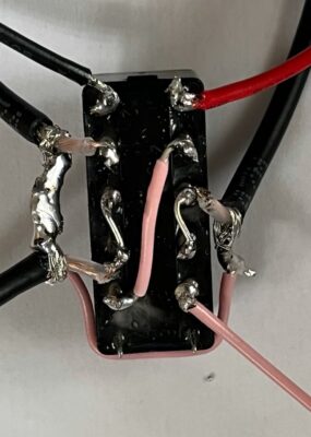
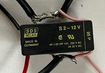
- Transmit-Receive Control relay triggered by a “PTT line” (ie. a connection from the rig which is grounded in transmit) – allowing the receiver to bypass the linear circuitry. The Relay is a SDS S2-12V (typical current draw 17mA, max operating voltage is 22V). I’m powering the relay from the main supply (12-21v) so I’ve used 220Ω + 380Ω 1/4w resistors in series to drop the voltage. It has this pin-out:-
(1) +10v always on
(2) NC : connected to (8)
(3) COM: RF in from the Transceiver
(4) COM: connected to (3)
(5) NO: RF to Amp input
(8) NC: from (2)
(9) COM: RF out to Antenna
(10) COM: connected to (9)
(11) NO: RF from Amp output
(12) = -ve (ie. the PTT line) - The Bias Control transistor TR1 (BS170) needs to be powered up and ready to go when the PTT line is grounded in transmit. It has a 100KΩ resistor between its gate and the PTT line with a 10nF cap across the gate and ground to deal with any stray RF on the line and in receive the amplifier input is effectively grounded preventing issues back in the receiver.
- Voltage regulator to provide 10v to Bias Control only.
- Low Pass Filter to follow
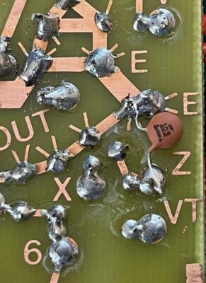
- As the layout was necessarily more distributed than normal, I used small ferrite cores on some of the DC wiring and thin coax for RF. Generally the rule is only ground one end of the coax, but it depends on the situation.

Commissioning
First Test (without LPF)
On a 12v supply, the following results using microphone:-
- About 0.5-1w input from Stone transceiver
- Around 7-8w output (approx 1w of which being reflected).
- Current through the 10v regulator was 110mA at rest so not much more than the power LED
- Adding the fan took the total to 220mA
- Transmit engaging the relay and TR1 took it to 500mA
At this point Tim suggested it was too much current for the 10v regulator. The fan and LED accounted for about 220mA at 10v so I decided to use a 50Ω 2w resistor as a voltage splitter to power those, leaving the 10v regulator to power the TR relay and Bias control.
Second Test (without LPF)
Again on 12v supply using a two-tone audio feed:-
- About 2w input from Stone transceiver
- Around 13w output (approx 1w reflected).
Again on 12v supply using microphone:-
- About 1w input from Stone transceiver
- Around 8w output (less than 1w reflected).
Observation: when going into transmit with the two-tone audio feed on the amp doesn’t always work (output = input), although you can hear the relay click. Best guess is that 2w input was drawing too much current in the IRF510s, starving the voltage regulator and so the relay.
At this point I changed the relay power to be the main rig supply with a dropping resistance of 220Ω + 380Ω 1/4w resistors in series
Third Test (without LPF)
On a 21v supply, the following results using microphone:-
- About 0.5-1w input from Stone transceiver
- Around 23w output (approx 1.5w reflected – harmonics!) = SWR 2.5 approx
Low Pass Filter
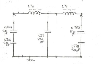
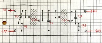
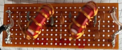
Following Tim Walford’s design in the Stone which is a Butterworth Double Pi LPF, I’ve repeated that design just a bit beefed up to take the higher power or more specifically RF voltage, which at 30w is about 110v p-p.
Inductors L70 and L71 are both 0.960μH with 13 turns wound on T68-2 toroid (heavier gauge enamelled copper and one less turn than Tim’s QRP design using a T50-2). The capacitors are all 820pF – C70A, C70B, C71, C73A and C73B rated at 100v rather than 50v. I would have opted for 200v ideally but availability was an issue.
Fourth Test (with LPF)
On a 21v supply, the following results using microphone:-
- About 0.5-1w input from Stone transceiver
- Around 20w output (< 0.5w reflected) = SWR 1.3 approx