
I often want to check reception on my FRG-7 when I’m listening on another radio but selecting the right frequency can be frustrating as the FRG-7 has an analogue dial. The Fine Tune and dial alignment controls can alter calibration too so some form of digital display would be very useful.
I didn’t want to alter the front dial so I decided I would use an external counter to display the frequency. As the MHz is obvious having selected that part of the frequency on the FRG-7 the only part of the frequency I need to see is the kHz part.
FRG-7 Circuit Description
The FRG-7 is a triple conversion superhet using the Wadley-Loop system which achieved remarkable frequency stability back in the late 1970s when the FRG-7 was released.
RF is amplified and passed through a LPF (cut-off 35 MHz) passing signals into the first mixer with a tunable hetrodyne oscillator (55.5 – 84.5 MHz). A 1 MHz oscillator produces selectable harmonics (front panel MHz selector) between 3 – 32 MHz which is mixed in producing the first IF of 54.5 – 55.5 MHz. The second mixer takes this with a 52.5 MHz oscillator to produce the second IF of 2 – 3 MHz. This is mixed with the VFO (main tuning) running 2.455 – 3.455 MHz to produce the third IF a 455 kHz signal which is filtered for LSB or USB and fed to the audio stages.
Extracting the VFO signal
The VFO at the LF end of its range with dial reading 0 kHz is at 3.455 MHz and at the HF end where the dial reads 1000 KHz the VFO is at 2.455 MHz.
So any digital display has to take the main tuning VFO frequency and subtract 3.455 MHz from it to run from 0 to -1000 but then lose the minus!
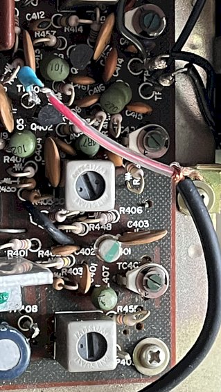
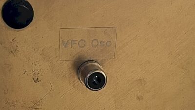
Test point TP404 has the buffered output of the VFO as it feeds into the third mixer and so I connected a 1 nF capacitor in series with a shielded connection to a RCA Phono socket on the back panel as below.

.
Dealing with the frequency
My Frequency Counter designed by Cumbria Designs kit built in 2007 has been pressed into service. It is extremely versatile and I have setup two programs in it to deal with the FRG-7, one for LSB and one for USB.
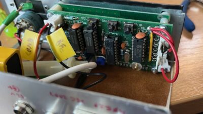
The counter works in either conventional Counter Mode or Radio Mode and it has 6 “Groups” of frequency calculations available to be programmed in for Radio Mode. To program this is done by:-
- Disconnect ground from pins 1 – 5 on the 8-pin group inside
- Switch on and press SEL for two seconds whilst in the intro screen to pick between defaulting to Counter Mode or defaulting to Radio Mode
- Continuing to hold SEL down will page through each of the Groups where you set a Group specific IF eg.
- Group B is set up for LSB by setting the IF to 3457.37
- Group C is set up for USB by setting the IF similarly on the other side of 455kHz
- After the Groups, you can set a multiplier factor for each group but that wasn’t necessary for the FRG-7.
- Grounding pin 6 will subtract the Group frequency above from the VFO input frequency.
By Grounding one of the pins 1 – 5 the Counter goes straight into a specific Group with Radio Mode settings at power up:-
- grounding pin 1 selects Group B = LSB
- grounding pin 2 selects Group C = USB
- removing ground from pins 1 or 2 goes into Counter Mode
The finished project works pretty well!