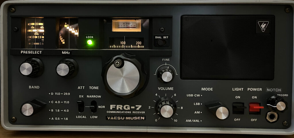
The Yaesu FRG-7 is a great receiver for its age, released in the late 1970s. It has some failings in SSB however. The narrow IF filter mod certainly improves matters but in today’s domestic QRM noisy bands some audio filtering can help combat the hiss.
This approach I used was to remove the front panel “record” socket and in its place put a dual linear pot to drive a phasing notch filter (See photo above although the camera perspective isn’t right. The notch control is immediately above the phone socket and not to the right as it appears).
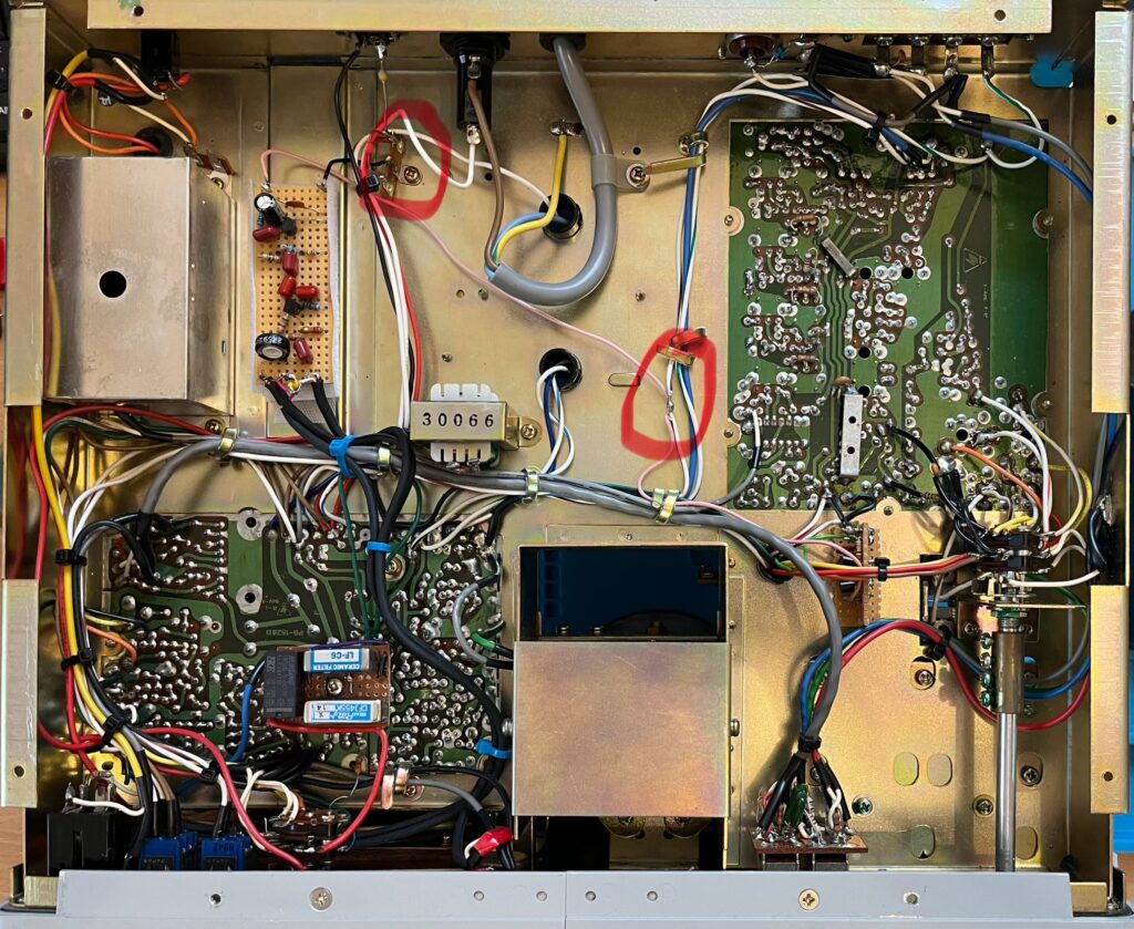
The circuit designed by Richard Booth G0TTL is simple to make and I have used it before in my Walford Sutton project; it worked very well. The notch filter is fitted in-line after the volume control (slider contact) en-route to the AF power amp (which is a white ended cable going to R453 2.2kR). An alternative would be to insert it after the junction of C440 0.2uF and L403 en route to the mode switch 3b which would make it only active for SSB however I felt there were times it would be helpful on AM too.
10.5v is available from voltage regulator Q111 2SD313 and 14.5v is available in the audio amplifier section. There are some Notes on IF/AF board which are very useful.
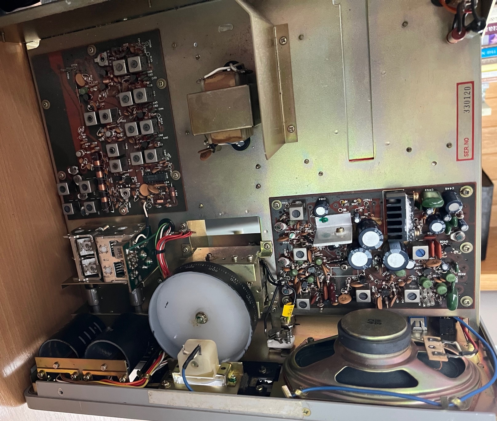
Installing the Notch Control on the front panel
The first step was to understand where the notch filter circuit board and the wiring from there to the front panel control and the input to the notch (the volume control slider contact) would go.
I decided to remove the Record socket as I felt it would never now be used and it would be a good position for the Notch control.
The Record socket removal required the Phone socket to be moved out of the way first but was fairly straight-forward.
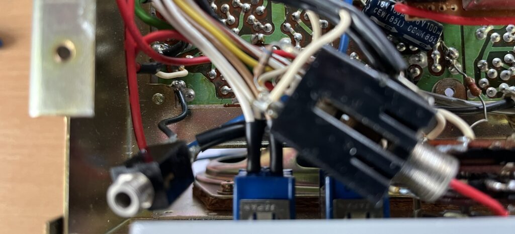
For info: the Record socket was originally connected as below:-
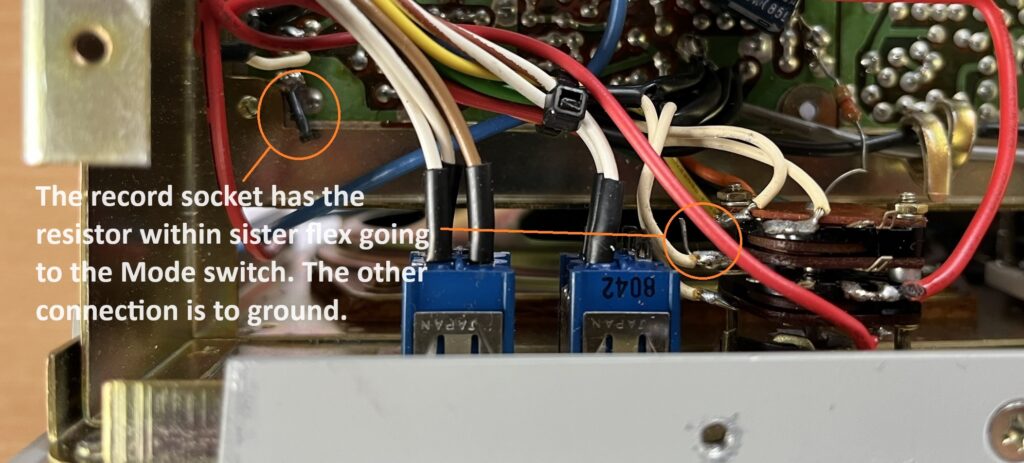
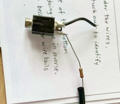
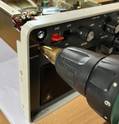
The front panel hole needed widening slightly
The front panel dual linear 10k pot was prepared for installing
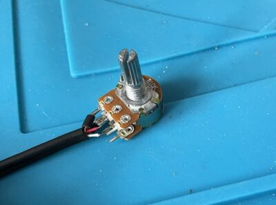
There isn’t much room so don’t get an oversized pot! Mine fitted snuggly next to the phone socket.
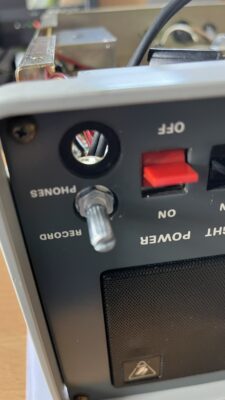
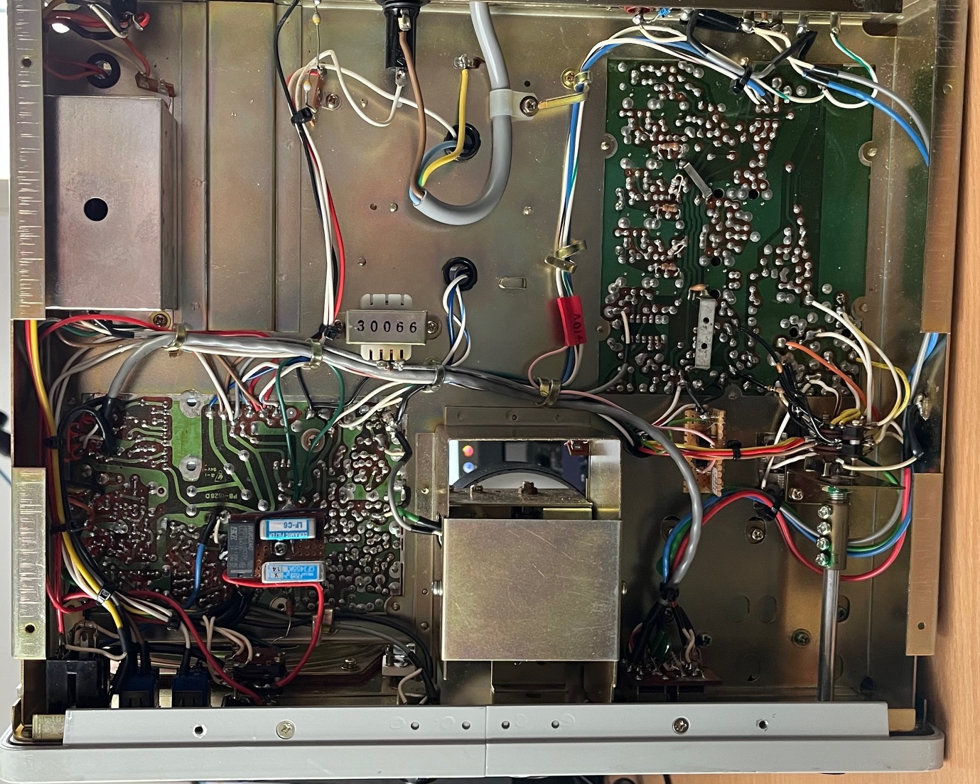
With the front panel complete, the notch filter was then built and installed. I decided that the space behind the IF/AF board looked good to locate the filter and to take 10.5v from the place I’d taken it before (see final photo of the underside view). I had worried whether 10.5v would be adequate for the filter but it turned out okay.
Building the filter
View Richard’s circuit design and details for phasing notch filter
There were a couple of labelling errors on Richard’s circuit: there are two R2s however it is easy to tell them apart and there is an unlabelled resistor on the emitter of TR1 which I have called Rx – this is 2.2k.
I built the filter on veroboard with the front panel connections to the Dual Linear “Notch” Pot and Volume Pot at the left end and Ground and +12v at the right end.
LHS connectors from top to bottom:-
- Output – to Volume control connection to AF power amp
- x
- x
- Notch end VR-A
- Notch common slider to VR-A and VR-B
- x
- Input – from Volume control slider
- Notch end VR-B
- Ground (later this pin was removed to create space)
RHS connectors from top to bottom
- 2nd row down: Ideally 12v but 10.5v works fine
- Bottom row: Ground from external DC input connection
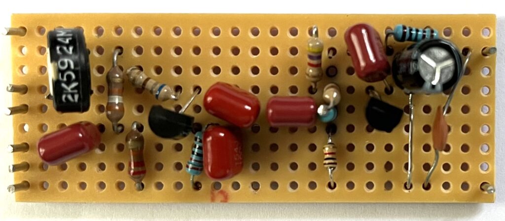
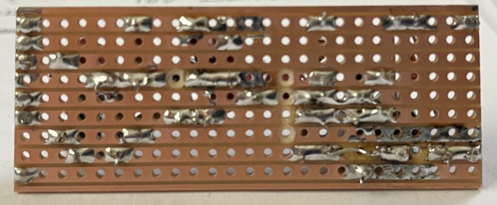
The layout broadly follows the circuit diagram. I adjusted the filter gain with the preset pot to be roughly equivalent to the previous input to the AF power amp from the volume control. Excuse the track repairs in the photo below – I found track lifted in a couple of places but not when it had been repeatedly warmed up which was odd.
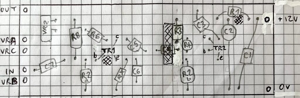
C7,*C5,*C6,C4,C3 = 100nF poly (*C5 & *C6 should be a matched pair – check they are if possible)
C2 = 100uF electrolytic
C1 = 10nF ceramic
VR1+2 = dual gang 10k linear pot
VR2 = preset 2k2 pot
R8 = 39k, R2a = 22k, R6 = 680R, Rx = 2.2k, R3 = 4k7, R2b = 1k, R4 = 1M8, R1 = 1k2
TR1,TR2 = BC182L (I used BC182Ls but any similar general purpose NPN transistor should work.)

The finished filter is positioned to the rear of the IF/AF board. The front panel connections are using screened audio cable which might not be necessary but the lead lengths are a bit long. I took Ground from the rear DC socket arrangement and 10.5v from the white lead in the photo where I had already ‘spliced’ it for power when I did the earlier IF filter mod (later covered with insulation tape of course!).
The filter itself is ‘stuck’ to the panel using sticky Velcro. Velcro might seem an odd choice perhaps but I was reluctant to drill through the metal sheet. I’ve found sticky Velcro to be a great way of fixing in these situations as it makes for a flexible fixing.
The finished circuit worked first time and I believe is a great addition to the FRG-7. I have labelled the control in the photo below but not removed the “Record” label in case it was ever reverted. The photo perspective makes it look as though it is in an odd position but it is actually immediately above the Phone socket.