 My Ciro Mazzoni Stealth Loop has continuous coverage from 10 to 40m. Gain is specified as equivalent to a dipole at 10m and down by half a s-point on 40m. Its win is the better signal to noise ratio which was obvious from the start. On the first day of pointing the antenna specifically at DX I had FT8 QSOs with Japan and Brazil.
What’s front and what’s back?
Years ago I had a QSO on 80m with someone using a mag loop. He was 59+10 with me and I was amazed when he described the small size of the loop. Then my late friend Peter Allan, G4NTA, lent me a mag loop he’d built with a hoola-hoop, a slinky and remote control for the variable capacitor operated by a motor with a slow motion gear box. If you get anywhere near a loop you throw the tuning out so you have to tune remotely. I already had an idea of the characteristics of a mag loop and what to expect.
It is directional: the front has quite a wide lobe, the back of the loop has a smaller lobe (1 s-point down on the front), the sides are the nulls (4 s-points down on the front). You might expect forward to be broadside to the loop but that isn’t the case. The forward direction is determined by where the Gamma Match (within the green circle) is connected to in relation to the feed point. Think of the loop as a bicycle wheel with the gamma match being the headlight on your bike shining RF in front of it (as shown by the green arrow)!
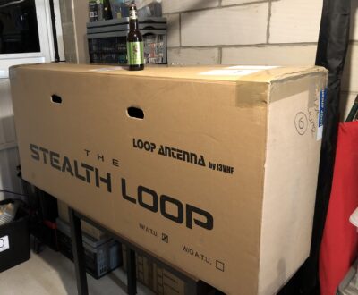
I ordered the Ciro Mazzoni Stealth Mag Loop from Martin Lynch & Sons. There’s nothing stealthy about the Ciro Mazzoni Stealth Loop box as you can tell with the beer bottle on top of the box (photo below), hi! The loop weighs 22lb and is made of welded heavy duty box section aluminium and stainless steel. It was well packaged and comes with an Auto ATU and manual on CD. This loop is outdoor use ready with the optional acrylic weatherproof cap which protects the capacitor on the top. I decided to get this too as it also keeps dust off the capacitor plates in the loft.
My QTH
I’ve had the luxury of good outdoor wire antennas in the past. My new QTH doesn’t have those opportunities and so indoor antennas in the loft space are the way I’ve chosen to go. EMC issues were my first anxiety so I’ve put Type 31 Ferrite clamps from Mouser on anything that doesn’t move but particularly PCs, CCTV system and power leads. Every last dB of RF counts in this situation so I’ve only used the best for the 15m coax run: “heavyweight” Messi & Paoloni PL259s and Ultraflex-10 or RG213; you won’t find RG58 in use for the main station coax.
We have an L shaped house with my 20m dipole sharing its space with Christmas, luggage and other assorted precious items/junk (delete as appropriate). The other side of the loft was intended for a cobweb antenna but I then realised it wouldn’t fit so this is where the loop has gone. Luckily I had installed an electric winch last year which was useful to get it through the loft hatch and then I had to weave it through the modern UK style of roof trusses to its final position.

Orientation, SWR and Ground Planes
Initially SWR was close to 3 on most bands. The loop needs to sit on a RF reflective surface or the ground. Using rolls of kitchen aluminium foil I created a loose aluminium sheet roughly an inch below the feet of the antenna. I had to take care to feed the coax and motor cable underneath the this reflective sheet as ideally these should feed to the loop vertically which isn’t easy to achieve.
The aluminium foil brought SWR down to around or just below 2 on all bands. I then placed the loop on a 3ft x 4ft sheet of “Faraday fabric” a thin copper/fabric weave this brought SWR down to 1.3 across (almost) all bands. The aluminium foil and Faraday cloth not only improve the SWR but also EMC and domestic noise. There’s a usable SWR bandwidth of around 40kHz on 20m without essential retuning although I would suggest retuning every 15kHz. What I hadn’t anticipated was that my 20m dipole, which is 12 feet (3.5-4m) away from the loop, would interact with it, increasing SWR on that band. I’ve tried to orientate the loop in a different plane to the dipole which has helped. Quite subtle movements of the antenna, the foil etc will affect SWR too.
 Originally I had thought I would be able to put the antenna on a rotator but there isn’t enough room in my loft for it to rotate freely. If I want to change its orientation it has to be done manually to avoid it hitting roof trusses. I downloaded an Azimuth map centred on my location from the useful website of Tom NS6T and overlayed that with an outline of my house to get a better idea of what to point the antenna towards.
Initially I thought “lets point it at USA/Canada” but that meant it was pointing at the shack and our noisy CCTV controller which meant the bands were noisy and it immediately knocked out my PC mouse and keyboard so no digimodes and some concern about where my RF was being showered! I did some EMF calculations and they suggested it was safe. For the timebeing I’ve decided to point at Japan with the rear is ‘pointing’ at Brazil. More locally, most of the UK and Scandanavia should also have good coverage on 40m.
ATU
The loop comes with an ATU although this has none of the usual coils and capacitors inside. It is really more of an antenna analyser measuring SWR and then determining what polarity of current to send to the motor which is mounted inside the loop structure to open/close the vanes of the giant capacitor on the top.
The ATU is shown above my FT-990 next to the Yaesu filter speaker. There’s a small keypad to manually control the ATU which displays the requested frequency and resulting SWR. The ATU will work in full auto mode via CAT for most popular transceivers built in the last twenty years but my FT-990 is older than that. I was wondering whether to build some middleware that would talk to the ATU and the FT-990 but I’ve decided not to as manual mode isn’t onerous.

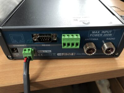 The ATU needs to be protected when using other antennas and so I have it connected via a Diamond CX201 antenna switch which grounds the unused port.
The two pin motor cable connector on the back is badly chosen as it doesn’t lock effectively. Mine doesn’t always stay in – the symptoms are that the blue motor light doesn’t come on and tuning goes on for a long time before it gives up.
The manual doesn’t explain the polarity of the motor cable at the connector on the back. I haven’t tried this but apparently if you get its the wrong way around it doesn’t cause damage (according the the manual) but it doesn’t work either. Whatever you do don’t ground one side of the cable as 24V will be sent straight to earth and you’ve just blown up your ATU!
ATU2 Power Supply Noise
The 24v Switch Moder Power Supply (SMPS) that came with my ATU2 was putting out a lot of hash on 40m, raising the noise floor by 10-12dB (up to 2 s-points); higher bands weren’t as badly affected. As I was initially using FT8 this wasn’t apparent to me until I was using SSB more. As the loop is some dB down at 40m compared to a dipole, loosing up to 2 s-points more to hash rules out using the loop for 40m except for strong signals over s9.
 I tried Fair-Rite Type 31 Ferrite clamps (half inch internal diameter) on the mains power input and the 24v output of the SMPS as well as on the motor cable from the ATU with as many turns as the cable would permit which should have stopped common mode noise but it didn’t. It appeared to me that the most significant problem was perhaps that the SMPS itself was radiating the hash which was then being picked up by the loop. I swapped to a professional grade 24v power supply that I have and the hash disappeared (for info you need 24v centre positive for the ATU2). The SMPS that came with the ATU2 has been sent back for inspection.
Performance and Updates
Check my log for an idea of how it is performing.
2nd Aug: Propagation has been poor the last few days. Despite that I pointed my loop towards Japan (the back is to Brazil) this morning and this afternoon I’ve had QSOs with Japan and Brazil on 17m FT8 which is confirming its directional properties.
3rd Aug: I had a go this afternoon and worked four Japanese stations reasonably easy on 17m using 20w FT8.
4th Aug: More Japan…I’m bored of working Japan now, hi! It seems it is working well at picking up digimode DX QSOs for where it is pointed.
Sep 2022: I’ve laid quite a few pieces of Faraday fabric now around the antenna. Mostly around both ends but also trying to screen others in my home on the floor below. It’s much easier to handle and I believe more effective for a reflective base than using aluminium foil. I’m still only using 20w FT8 (the duty cycle for FT8 is close to AM) and haven’t really tried to do any SSB yet. I’m under no illusions that DX stations have probably got better antenna arrangements than I have but here are my most distant DX so far.

Autumn 2022: I’ve had two SSB contacts, one on 17m with a Norwegian above the Arctic Circle with a 59 report and one on 40m with a French station with a 51 report. I had a good 59+ each way inter-G contact on 40m with GB100BBC, located at the BBC Woofferton shortwave transmitting station in Shropshire, England. Digimodes have got me into Australia a few times.
Spring 2023: More SSB contacts on 17m across Europe with FT8 worldwide. The specifics of its directional nature are becoming more apparent. My loop is pointed north-east-north so Finnish stations are ten a penny and Thailand and Japan are usually workable. On 10m I was frustrated in being able to work the Far-East easily but couldn’t work stations in South America or Africa despite hearing them with good reports. So I believe the directional aspects are more pronounced on 12m and 10m than 17m and lower frequencies.
Autumn 2026: The FT-990 worked fine but I’ve been using a FT-747GX over the last few years mostly for FT8. I’ve swapped out the 747 for a FT-710 which is much easier to work with and control remotely.
Instruction manual (from DX Engineering)
Some Troubleshooting Findings
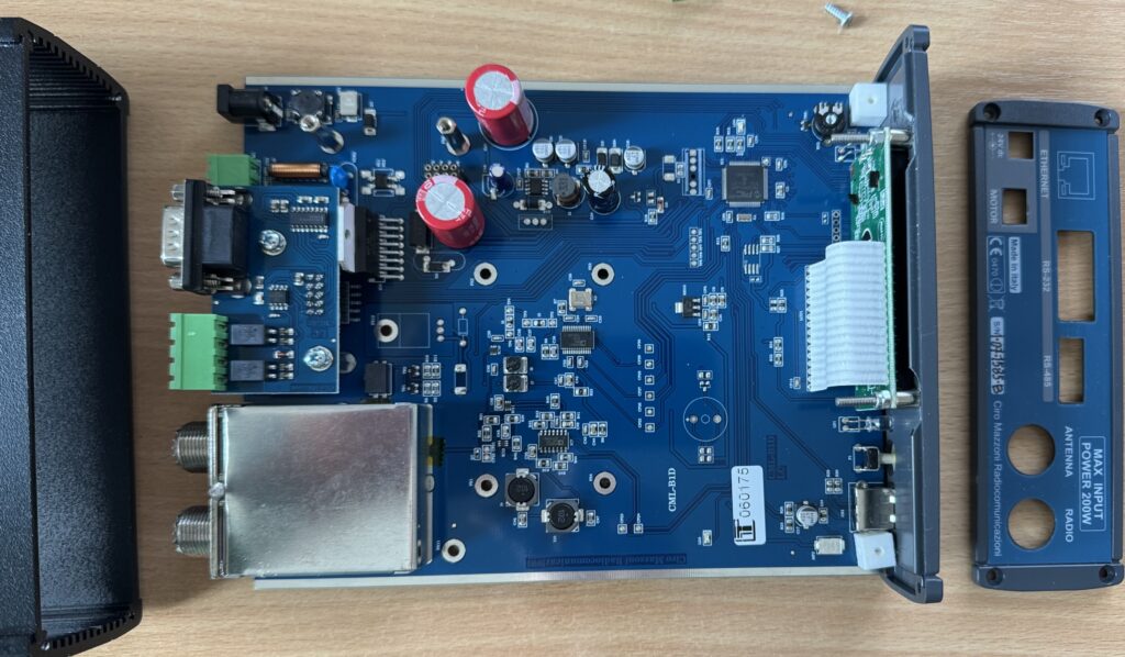
The ATU2 can be a bit quirky. Internally it looks like below. It can be accessed by unscrewing the front and back panel (eight) screws, easing off the back panel and sliding the PCB forward out of the case.
Entering a frequency on the keypad, the ATU2 was showing the red tuning light on but no blue motor activity light. After 30 seconds or so it resulted in the message “Tuning Fail No Resonance”. I did brief check on the Antenna connections (PL259 and Motor cable) and they seemed okay initially.
Manually tuning mode was informative: using the [backslash/] key, enter a frequency and then use the 9 / 3 keys to open or close at high speed showed + or – 20v on the motor connector and the blue light would stay on indicating current driving the motor.
The problem was the “heavyweight” Messi & Paoloni PL-259 connector at the antenna; they are hard to tighten securely. Two or three weeks later I had a similar issue this time with message “Motor Fail No Load”. I wirewoolled the centre pins of the SO-239 and the PL-259 and tightened the connector with a spanner this time.